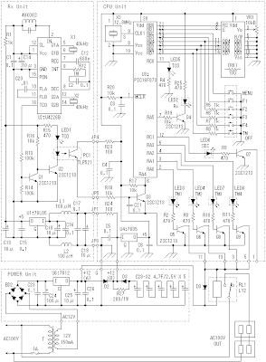
Tm 1520 ch diagram wiring clock 47d change Car stereo in home wiring diagram Tork time clock wiring diagram
Standard Electric Time Company Technical Information
Alarm clock radio schematic schema gr next Wiring diagram technical time clocks electric movement information clockhistory Standard electric time company technical information
Wiring caraudionow aftermarket
Wiring intermatic timer diagram sprinkler diagramsRadio and clock stopped working: hello! both the radio and clock Circuits wiringConnected clock radio wiring diagram hackster.
Wiring diagram ac grand maxDiagram wiring clock master tower company gps Clock time wiring diagram wire electrical 110v off power electrician callWiring diagram r32 skyline clock problems audio electric australia engine dash sau article.

Tork clock time wiring diagram circuits control manuals timers waterheatertimer telsa likes
Circuit diagram seekicRadio alarm clock under repository-circuits -20361- : next.gr Intermatic timer wiring diagramTork time clock wiring diagram.
Electrical educationWiring diagram for a tower clock with a master clock and gps Electric problems with clock and audioClock wiring diagram.

Basic automatic clock wiring diagram by lumichron
Wiring diagram timer hager grand ac max switch analog muditClock radio signal time schematic detector Gps set clockLights wiring diagram clock time volts electrical control electric watt mh want cell asking question thank again.
Radio, alarm clock and thermometerTork clock timer intermatic timers wired waterheatertimer 1101 1103 contactor manuals motor t101 controller shall capable Clock wiring diagram automatic basicAlarm thermometer clock radio system.

Gps clock arduino schematic set wiring
Connected clock radioI have 3 400 watt mh lights 208 volts that i want to have on a time Radio and clock stopped working: hello! both the radio and clock.
.


GPS Set Clock

Electrical Education | Electricians Training - How to wire a Time Clock

Car Stereo In Home Wiring Diagram - Collection - Faceitsalon.com

Wiring Diagram Ac Grand Max

Standard Electric Time Company Technical Information

Radio, alarm clock and thermometer - all in one system - Do It Easy

Basic automatic clock wiring diagram by Lumichron - Lumichron Clock Company

Resources - Factory wiring locations for adding additional circuits